View Index by Level
RANDOM PAGE

SITE SEARCH

LOG
IN

SIGN UP

HELP

Truth Tables


This is the AQA version closing after June 2019. Visit the the version for Eduqas instead.

To gain access to revision questions, please sign up and log in.

Everyone

Tasks

  1. Draw the circuit diagram symbols for the following two input logic gates ...
      AND          OR           NAND         NOR          XOR          NOT  


  2. Complete truth tables for ...
      AND          OR           NAND         NOR          XOR          NOT
      A B  Q       A B  Q       A B  Q       A B  Q       A B  Q       A  Q       
      0 0          0 0          0 0          0 0          0 0          0
      0 1          0 1          0 1          0 1          0 1          1
      1 0          1 0          1 0          1 0          1 0
      1 1          1 1          1 1          1 1          1 1
      
  3. A logic circuit with two inputs has an output that goes high when input A is High and input B is Low.
    Draw a circuit diagram using two gates that would achieve this.

    2 Detector
     
  4. A logic circuit based on a counter has an output that goes high when the input is 2 or 3.
    Draw a circuit diagram using only AND, OR and NOT gates that would achieve this.

    2 OR 3
     
  5. A logic circuit based on a counter has an output that goes high when the input is 0 or 1.
    Draw a circuit diagram using only AND, OR and NOT gates that would achieve this.

    0 OR 1
     
  6. Complete the truth table for this circuit and state the decimal input numbers which cause the output to be high.

    N OR N
     
  7. Modify the circuit in Q 4 to use only NAND gates. Draw rings round any redundant gates.


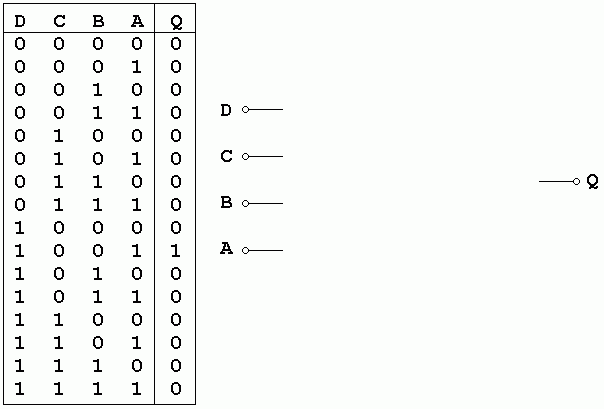
  8. Draw a logic circuit using only NOT and AND gates to give a high output if the input value in decimal numbers is nine as shown in the truth table.

    9 Detector


reviseOmatic V3     Contacts, ©, Cookies, Data Protection and Disclaimers Hosted at linode.com, London